For Routine & QA Testing of MV, HV and EHV Dry Type Bushings, Current Transformers and Cable Terminations
RHM International’s marketing plans required expansion of their product manufacturing facilities outside of China. As a first step in this plan a new manufacturing plant to serve the North American and European markets was constructed in the USA near Hudson, New Hampshire. A key component of the new plant was the HV test laboratory which was designed to perform mainly routine tests, as well quality assurance and R&D tests for RHM products with nominal voltages up to 500-600kV, including but not limited to instrument transformers, bushings and cable terminations. Routine and quality assurance tests verify that the design is being produced in a consistent manner under controlled manufacturing processes. It is therefore essential that the manufacturer have the in-house HV testing facilities to be able to monitor and measure the insulation performance (e.g. withstand and impulse voltage stresses, dielectric losses, partial discharge, etc.) of the final ex-works product.
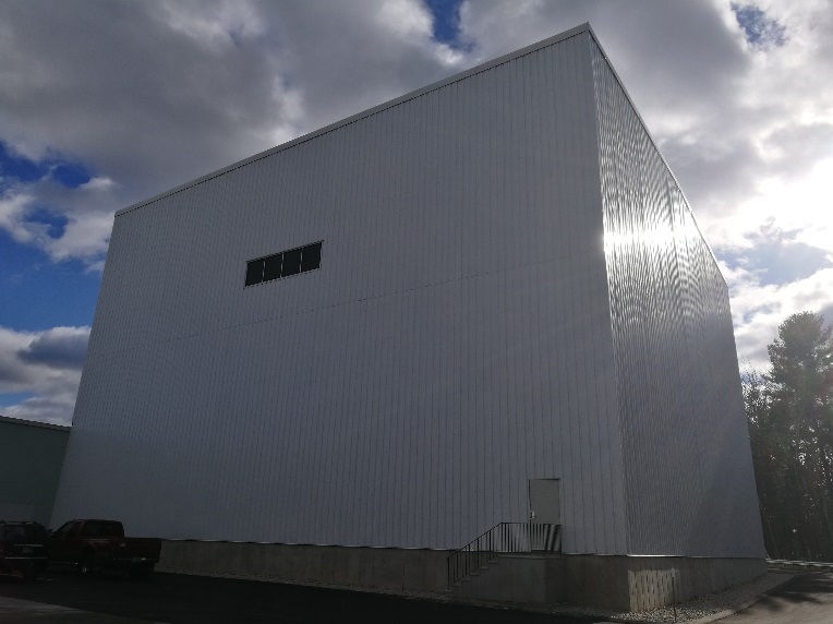
RHM International's New High Voltage Testing & QA Facility in New Hampshire
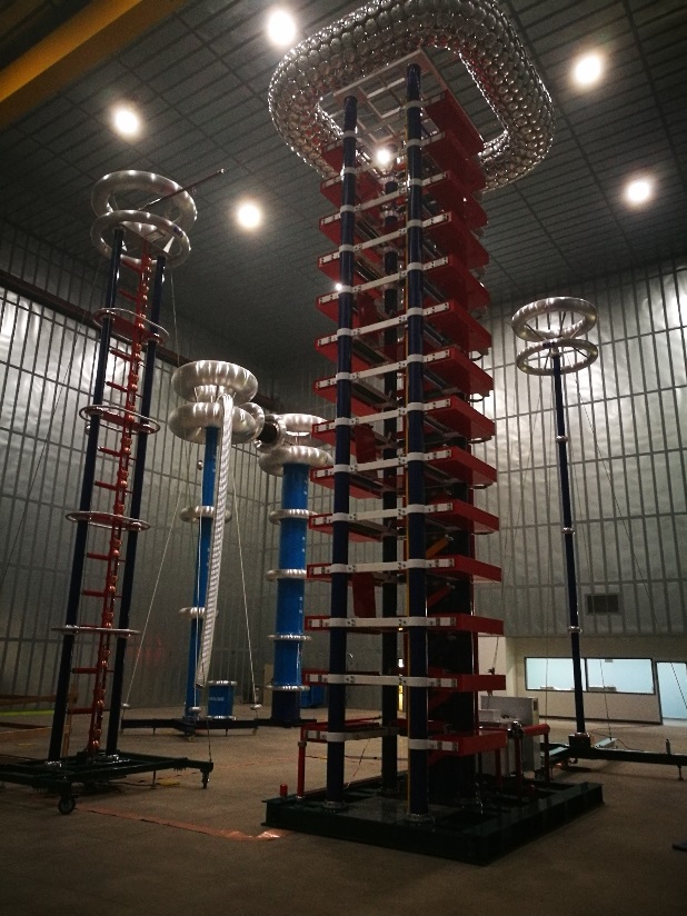
Inside View of Test Bay
HV Lab Grounding System & Faraday Cage
In this month’s article we will cover the design and construction of the lab’s grounding system and Faraday Cage (Part 1). Next month’s article (Part 2) will cover the test equipment specifications, the layout of the test floor and the testing capabilities of the new lab.
The floor area of the new HV lab is 784 m² (28.0 m x 28.0 m) with a ceiling-to-floor clearance of 17.5m. The HV lab is completely shielded electromagnetically with a shielding efficiency value of better than 55dB between 0.5MHz and 1.6MHz. A floor level control room is also a part of the Faraday cage. A low resistance ground path for the HV lab is provided by a 51.0 m x 35.0 m composite grounding grid with a grounding resistance value of less than 1.5Ω. 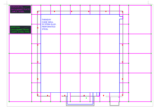 Isolation transformers were installed to isolate all power feeds into the Faraday cage. Power line filters were welded to the Faraday cage and installed between the isolation transformers secondary windings and control panels located in the cage.
For staff and equipment safety, and to ensure measurement accuracy and precision, especially sensitive partial discharge measurements down to a very few pico-coulombs, a high shielding efficiency and low grounding resistance has to be implemented in the design. In principal, a six-sided Faraday cage enclosure shields against the penetration of electromagnetic waves while a low grounding resistance improves the measuring accuracy and precision, prevents control circuit overvoltages and ensures a reliable path to ground for staff and equipment safety.
According to a geotechnical study the soil resistivity of the site was measured to be around 600Ω•m, which is extremely high for an HV lab location. Special measures had to be taken to decrease the grounding resistance, which included:
- Installation of 66 vertical galvanized steel pipes (70mm diameter and 3mm wall thickness) that were driven 2m below the floor. Of the 66 vertical steel pipes installed 56 of them were 3m in length and 10 were 8-10m in length. The longer steel pipes were needed to access the water table to get further ohmic reduction.
- Horizontal galvanized steel plates 40mm by 5mm were used to connect all the vertical grounding pipes below ground level.
The HV Lab uses a double wall construction with insulation between the walls. The inner walls and ceiling form 5 sides of the Faraday cage and are constructed of 0.635 mm (24ga) welded steel sheet panels.
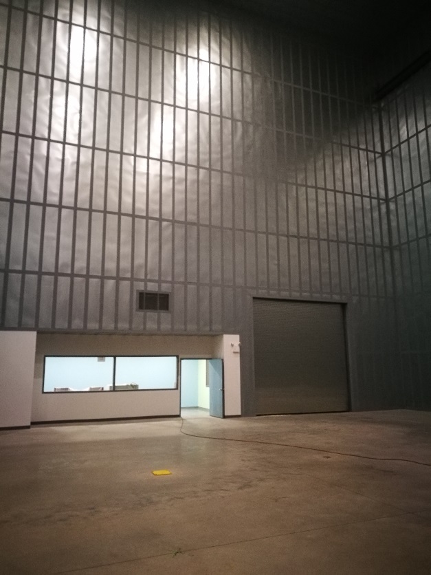
Walls, Ceiling and Control Room Shielding
Perforations are used to eliminate echo and shorten the reverberation time. It has been found that a reverse stagger perforation pattern using 0.6 mm holes in a 60 degree 3.6 mm equilateral triangle configuration giving an open area percentage of less than 3% works well. The steel sheets are welded onto interconnected modular steel frames and are fully connected to the extended plate of the ground shield – the sixth side of the Faraday cage. The ground shield is made of double layers of steel mesh embedded in the concrete floor of the lab. Galvanized 1.2 mm (18ga) expanded steel mesh measuring 20mm LWD by 9mm SWD forms the upper layer shield and 10mm diameter rebar formed in a 150mm by 150mm square mesh reinforces the concrete and provides an auxiliary shield layer.
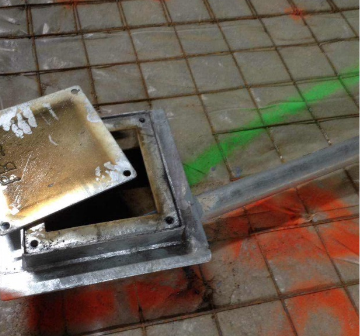
Ground Shield – Auxiliary Rebar Layer

Ground Shield – Expanded Steel Mesh Upper Layer
To maintain the integrity of the shielding system, all doors are metal clad doors with metal frames connected to the shielding system. Bronze spring finger contacts are used along the entire door / frame perimeter. A large motor driven coiling door moving in overlapping frames is used to allow the moving of test objects in and out of the cage.
