The next series of articles in our blog will review the history and development of HV dry type current transformers (CTs); and in particular the line of dry type current transformers that was developed in the 1980’s and later patented in the 1990’s and trademarked as HV DryShield®. For decades utilities have been seeking to eliminate the use of oil/paper or gas in their substation equipment’s insulation. The unmatched level of success of the HV DryShield®.line of CTs has met for the first time these expectations.
These articles will cover the following topics:
Part 1 – Structure, Insulation and Characteristics of HV Dry Type CTs
Part 2 – Ratings and Service Conditions of HV Dry Type CTs
Part 3 – Grading Condenser and Uniform Electrical Field Design of the HV DryShield® CT.
The inventors and developers of the first dry type high voltage insulation technology used in wall bushings and current transformers were a husband and wife team of Tsinghua University electrical engineers – Weishu Huang and Ruzhang Wang who during their careers at the Electrical Power Research Institute (EPRI) in Beijing led the research, development, and testing of successive generations of HV dry type current transformers and wall bushings. When they retired from EPRI (Beijing) they created a new company, TR Electric, to promote and manufacture HV DryShield® products which also included the manufacturing of the key components like PTFE tapes, silicone rubber sheds and secondary windings, leaving no place for unchecked quality inconsistency. Today TR Electric is a sister company of RHM International.
This technology has a proven service record with close to 100,000 wall bushings and current transformers ranging from 35 kV – 220 kV and 35 kV – 600 kV respectively in operation in all types of operating environments on T&D systems in many parts of the world.
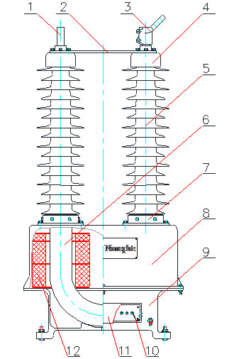
Basic Structure of the HV DryShield® LRGBJ Series Current Transformer
RHM International’s LRGBJ line of current transformer uses a “U” shape primary and sealed, waterproof dry-type secondary windings making it an immediately recognizable product in a substation.
The primary consists of one or more turns of current-carrying conductor made of copper or aluminium depending on the specified continuous primary current and short-time thermal current ratings and a condenser graded insulation design that uses a high grade polymer film for its main insulation material. The principal polymer used is PTFE (PolyTetraFluoroEthylene). PTFE is an excellent electrical insulation material with an extremely low dielectric dissipation factor and high physical, thermal and chemical stability. Silicone gel is used along with the PTFE tape as a capillary interface to fill the micro gaps and expel air bubbles in the tape. Using these materials in the build of a condenser graded structure results in a current transformer with small partial discharge, small tanδ and high withstand voltage. Finally, a high-grade heat shrink tubing is installed to seal and protect the primary condenser.
The sealed primary and secondary windings are then seated and fixed in a base box located at ground potential (see Figure 1) with the final position of the secondary windings being lower than the primary winding’s last grading screen. Fixing flanges on the base box lid ensure a mechanically strong connection of the primary condenser to the base box. The secondary windings are terminated in a secondary terminal box located on the side of the base box. Also located in the secondary terminal box is the capacitive test tap providing a solid connection to the last grading screen of the primary condenser.

Figure 1 Dry type CT Basic Structure

The external insulation housing is formed from individual high quality silicone rubber sheds that have been designed and formed to overlap each other and exactly fit the profile of the finished primary condenser. The sheds are glued directly to the condenser structure so no interstitial insulating filler is required.
An insulated connection board connects two arms of the “U” shape primary winding in order to stabilize and enhance the CT’s mechanical strength. When a dual current primary is specified the series/parallel connection link board for changing the primary winding’s ratio is also located here.
Characteristics of the HV DryShield® LRGBJ Series Current Transformer
The proprietary insulation technology and simple mechanical design used in the LRGBJ current transformer provides reliability and safety characteristics not available from traditional technologies for a very important piece of HV equipment in the T&D grid. Some of the more noteworthy characteristics being:
- High reliability and maintenance-free
- Lightweight
- Excellent dynamic and thermal stability
- Wide range of service conditions
- Suitable for outdoor storage
- Customized Design and Short lead times
Using composite material (such as PTFE and silicone rubber) as the main internal and external insulation to replace oil-paper, gas, porcelain, cast epoxy, etc. ensures a leak-free, explosion-resistant and maintenance-free operation.
Significant weight reduction due to no oil and porcelain.
The “U” shape structure with its large distance between the two arms reduces the electric forces under normal or short circuit conditions. The main insulation has a very low dissipation factor and remarkable stability over a wide range of frequency and environmental conditions, which ensures an excellent thermal stability.
PTFE, the main internal insulation has a continuous service temperature range from -260°C to +260°C and silicone rubber, the main external insulation has excellent hydrophobicity and tracking and erosion resistance. This combines to make a CT that is able to operate at severe environmental temperatures and in heavily polluted areas.
Both the primary and secondary windings are sealed designs and impervious to water allowing them to be stored outdoors.
No vacuum and drying processing and a simple assembly process allows for customized designs and shorter lead times.
